Advanced Hydrogen Turbine


Background

Siemens Energy, along with numerous partners, has an ongoing U.S. Department of Energy (DOE) program to develop hydrogen turbines for coal-based integrated gasification combined cycle (IGCC) power generation that will improve efficiency, reduce emissions, lower costs, and allow for carbon capture and storage (CCS). Siemens Energy is expanding this program for industrial applications such as cement, chemical, steel, and aluminum plants, refineries, manufacturing facilities, etc., under the American Recovery and Reinvestment Act (ARRA). ARRA funding will be utilized to facilitate a set of gas turbine technology advancements that will improve the efficiency, emissions, and cost performance of turbines for industrial CCS. ARRA industrial technology acceleration, application, and adaptation will also benefit advanced hydrogen turbine development and existing machines in typical utility applications.

This project is managed by the DOE’s National Energy Technology Laboratory (NETL). NETL is researching advanced turbine technology with the goal of producing reliable, affordable, and environmentally friendly electric power in response to the nation’s increasing energy challenges. With the Hydrogen Turbine Program, NETL is leading the research, development, and demonstration of these technologies to achieve power production from high hydrogen content fuels derived from coal that is clean, efficient, and cost-effective, minimizes carbon dioxide (CO2) emissions, and will help maintain the nation’s leadership in the export of gas turbine equipment.

Project Description

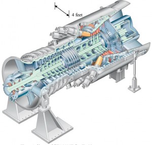
Siemens Turbine
Click to enlarge

Under the ARRA funded program, Siemens Energy will focus on advancing state-of-the art large natural gas fired turbine technology to produce turbines specifically designed for operation on hydrogen and syngas fuels derived from industrial processes that capture a large percentage of CO2. Advanced technologies and concepts will be evaluated, down selected, and validated. The advanced technologies, component designs, and manufacturing processes will be developed and verified in sub-scale and full-scale tests and process verifications to demonstrate that the program goals can be achieved. Some of the key enabling technologies needed are as follows:

• Fuel-flexible, ultra low NOX, long-life combustion system operating at the increased firing temperatures needed to achieve high efficiency. Siemens will work to develop a premixed combustion system capable of operating on hydrogen fuel at high temperatures with minimal dilution flow. As part of this development, modeling tools for thermal acoustics and computational fluid dynamics will be adapted for hydrogen fuels and validated with test data. The primary path for the hydrogen combustor is a modification of the current Siemens premixed natural gas burner to operate on hydrogen. In addition, as risk mitigation, several alternative combustion technologies will be evaluated to determine if they can provide an improvement for high-temperature hydrogen operation.

• Development and optimization of higher temperature material system (base alloy, bond coat, and thermal barrier coatings [TBCs]) capabilities that allow operation in challenging environments, thus ensuring that the turbine components achieve high reliability and long life.

• Advanced manufacturing processes and techniques essential to producing the novel turbine cooling schemes that are being pursued in this program. Siemens will be producing full-sized engine parts using advanced core making technology, performing investment casting trials, conducting destructive and non-destructive evaluations, machining prototype parts using a proposed production process and conducting full-scale engine testing on final products.

• New sensors and diagnostics to allow more efficient, fuel-flexible, and safe gas turbine operation. Customer interviews determined key sensing needs and sensor specifications for these needs. Based on these results, Siemens will work with sensor vendors to design, develop, and validate sensor designs for engine validation or use in on-line control.

Goals/Objectives

The objective of the ARRA activity is to identify a set of gas turbine technology advancements that will improve the efficiency, emissions, and cost performance of gas turbines for industrial applications with CCS. This extension will accelerate the key technologies needed to significantly improve the efficiency of gas turbines in industrial applications, apply these technologies to the advanced hydrogen turbine, and adapt to existing turbine frames as applicable.

Government funding for this project is provided in whole or in part through the American Recovery and Reinvestment Act.

AWARD NUMBER: DE-FC26-05NT42644
Mass Exodus From The U.S. Workforce – Nov. 2013

The unemployment rate has been declining, but so has labor force participation. Media attention tends to focus on the former and to ignore the latter; as a result, some people wrongly assume that the employment situation is improving and that it’s only a matter of time before things get back to “normal.” Here are some sobering facts.

Click to enlarge

Click to enlarge

The November 2013 Labor Department report shows a clear decline in both unemployment and labor participation. While the economy added more jobs than expected –incidentally, largely in the low-wage retail and leisure sectors- more people dropped out of the workforce altogether. In all, 91.5 million people of working age –37.2% of the labor force- are not working. At this rate, they will surpass the number of workers in about four years.

There are several reasons for this, all negative. While some baby boomers will have non-government income from retirement savings, that will require selling securities. If the number of sellers exceeds the number of buyers, asset prices may decline. If that happens some may be forced to sell even more, triggering a nightmarish cycle. And that’s not all. Generally, people on fixed incomes budget more and spend less, bad for local businesses –but not quite as crucial for multi national corporations- and the government, whose revenue stands to decline accordingly.

Speaking of taxes, safety-net programs such as welfare, food stamps and the new medical insurance program, as well as the military, need lots of taxation to support them; if tax receipts decline, the government will have to decide, gridlock permitting, whether to accelerate the rate of deficit spending, cut expenditures, increase tax rates, or some combination thereof. In any event, the trend does not herald better times ahead, particularly for working class people. We need a new, powerful incentive to get back to work.

Aquafacture Details

Characteristics

Basically, aquafacture is a process that uses a dedicated grid of solar-generated electricity and seawater to produce hydrogen. The hydrogen is then pumped up to a nearby mountaintop to a cluster of 5 or more power plants using Advanced Hydrogen Turbines (currently under development) that do not require fuel cells. The hydrogen is burned and its byproduct –pure water- is captured and condensed. The water is then pressurized and piped down using gravity exclusively to a series of terraced hydroelectric plants on the same mountain. Dams are unnecessary. Thus, the electricity generated by these additional hydro plants using the same manufactured water consecutively would not only recover the energy loss inherent in producing the hydrogen, together they would actually generate a surplus of energy proportional to the number of hydro generators and the volume of manufactured water.

Requirements

1) One natural below-sea-level depression in a desert near an ocean or mountains close to an ocean.

2) A sea-level canal to fill the depression by gravity.

3) Numerous dry lake beds near the depression adjacent to or surrounded by suitable mountains, to expand the system.

4) Absence of war or the threat of war.

Advantages

Unlike coal, a solid, aquafacture’s raw materials –seawater, solar energy and gravity- require no mining. Hydrogen can be transported by pipelines or tankers, depending on the destination. The process generates enough electricity and water to support an entire new economy anywhere regardless of drought. For the first time in recorded history, humans would be able to use renewable energy exclusively to “grow” their own water  anywhere and to make a profit from it.

Basics

Introduction

We are now in the 21st century, the age of weapons of mass destruction, computers, the internet, and interplanetary exploration. But when it comes to water, we still depend on natural precipitation to fill our reservoirs, lakes, rivers and aquifers, much like ancient civilizations did thousands of years ago. We may have learned how to cultivate our food, but we certainly have not yet figured out how to manufacture pure water cheaply and abundantly wherever and whenever we need and want it. That, of course is precisely what we need to make our deserts green and reduce carbon dioxide in our atmosphere, a step in the struggle to reverse global warming. It would also meet mankind’s current and future demand for water anywhere, and help prevent unnecessary wars and famine.

We live in a water world. 70% of the world’s surface is covered in water. Yet the vast majority of it – around 97% – is salt water. Another 2% is locked up in ice caps and glaciers. Only around 1% of the world’s water is fresh, and of that, humanity can only easily access about a tenth, or 0.1%. For decades, desalination and electrolysis have been considered deeply anti-environmental processes, primarily because they consume enormous amounts of energy and release huge amounts of greenhouse gases. Not necessarily.

The Concept

If we found a way to use solar energy exclusively to disassociate saltwater molecules to produce hydrogen at a profit, it would be possible to build a global infrastructure to burn the hydrogen and produce water anywhere in the world. The problem with that is that there is a net energy loss, and hence financial, associated with hydrogen production. The laws of energy conservation dictate that the total amount of energy recovered from the recombination of hydrogen and oxygen must always be less than the amount of energy required to split the original water molecule. We cannot remove this obstacle, but we can go around it by invoking other equally immutable laws:

1) Hydrogen is the lightest element in the periodic table, so light that in its gaseous form it quickly rises in the atmosphere and dissipates. This is extraordinarily useful because it means that the force required to pump gaseous hydrogen upward is minimal; it’s already headed that way.

2) In any volume of water, the ratio of hydrogen atoms to 1 molecule of water is 2:1. The mass of a mole of water molecules is 18g on average, so 2 moles of hydrogen atoms are in 18g of water. There are 3785.4g of water in a gallon (assuming the water is 39.2 degrees F), so there are 3785.4/18 = 210.3 moles of water molecules in a gallon. For every water molecule there are two hydrogen atoms giving 2 x 210.3 = 420.6 moles of hydrogen in a gallon of water. A mole is 6.023 x 10²³ atoms. So there are 420.6 x 6.023 x1023 = 2.533 x 1026 hydrogen atoms in a gallon of water. Since each mole of hydrogen atoms has a mass of 2g, there are 420.6g of hydrogen in every gallon of (rather cold) water.

In other words, 1 mole of water is 9 times heavier than 1 mole of hydrogen. It is this difference in mass that makes it possible to use gravity to not only recapture the energy loss but to actually generate a surplus, manufacture pure water, and make a profit -simultaneously. Currently, there are no known commercial facilities anywhere taking advantage of this fact.

Electrolysis

Principle

An electrical power source is connected to two electrodes, or two plates (typically made from some inert metal such as platinum or stainless steel) which are placed in the water. Hydrogen will appear at the cathode (the negatively charged electrode, where electrons enter the water), and oxygen will appear at the anode (the positively charged electrode). Assuming ideal faradaic efficiency, the amount of hydrogen generated is twice the number of moles of oxygen, and both are proportional to the total electrical charge conducted by the solution. However, in many cells competing side reactions dominate, resulting in different products and less than ideal faradaic efficiency.

Electrolysis of pure water requires excess energy in the form of overpotential to overcome various activation barriers. Without the excess energy the electrolysis of pure water occurs very slowly or not at all. This is in part due to the limited self-ionization of water. Seawater has an electrical conductivity about one million times more than pure water. Many electrolytic cells may also lack the requisite electrocatalysts. The efficacy of electrolysis is increased through the addition of an electrolyte (such as a salt, an acid or a base) and the use of electrocatalysts.

Currently the electrolytic process is rarely used in industrial applications since hydrogen can currently be produced more affordably from fossil fuels.

Solar Cells 44.7% Efficient

Press Release

September 23, 2013

The Fraunhofer Institute for Solar Energy Systems ISE, Soitec, CEA-Leti and the Helmholtz Center Berlin jointly announced today having achieved a new world record for the conversion of sunlight into electricity using a new solar cell structure with four solar subcells. Surpassing competition after only over three years of research, and entering the roadmap at world class level, a new record efficiency of 44.7% was measured at a concentration of 297 suns. This indicates that 44.7% of the solar spectrum’s energy, from ultraviolet through to the infrared, is converted into electrical energy. This is a major step towards reducing further the costs of solar electricity and continues to pave the way to the 50% efficiency roadmap.

Back in May 2013, the German-French team of Fraunhofer ISE, Soitec, CEA-Leti and the Helmholtz Center Berlin had already announced a solar cell with 43.6% efficiency. Building on this result, further intensive research work and optimization steps led to the present efficiency of 44.7%.

These solar cells are used in concentrator photovoltaics (CPV), a technology which achieves more than twice the efficiency of conventional PV power plants in sun-rich locations. The terrestrial use of so-called III-V multi-junction solar cells, which originally came from space technology, has prevailed to realize highest efficiencies for the conversion of sunlight to electricity. In this multi-junction solar cell, several cells made out of different III-V semiconductor materials are stacked on top of each other. The single subcells absorb different wavelength ranges of the solar spectrum.

“We are incredibly proud of our team which has been working now for three years on this four-junction solar cell,” says Frank Dimroth, Department Head and Project Leader in charge of this development work at Fraunhofer ISE. “This four-junction solar cell contains our collected expertise in this area over many years. Besides improved materials and optimization of the structure, a new procedure called wafer bonding plays a central role. With this technology, we are able to connect two semiconductor crystals, which otherwise cannot be grown on top of each other with high crystal quality. In this way we can produce the optimal semiconductor combination to create the highest efficiency solar cells.”

“This world record increasing our efficiency level by more than 1 point in less than 4 months demonstrates the extreme potential of our four-junction solar cell design which relies on Soitec bonding techniques and expertise,” says André-Jacques Auberton-Hervé, Soitec’s Chairman and CEO. “It confirms the acceleration of the roadmap towards higher efficiencies which represents a key contributor to competitiveness of our own CPV systems. We are very proud of this achievement, a demonstration of a very successful collaboration.”

“This new record value reinforces the credibility of the direct semiconductor bonding approaches that is developed in the frame of our collaboration with Soitec and Fraunhofer ISE. We are very proud of this new result, confirming the broad path that exists in solar technologies for advanced III-V semiconductor processing,” said Leti CEO Laurent Malier.

Concentrator modules are produced by Soitec (started in 2005 under the name Concentrix Solar, a spin-off of Fraunhofer ISE). This particularly efficient technology is employed in solar power plants located in sun-rich regions with a high percentage of direct radiation. Presently Soitec has CPV installations in 18 different countries including Italy, France, South Africa and California.

Solar Batteries

June 21, 2013

SMA Solar, Germany’s largest solar company and the world’s largest maker of inverters, a device to feed solar-generated energy into the electricity grid, announced the introduction of a new battery set to store surplus daytime solar energy for up to three hours of nighttime use.

The new combined inverter battery will give a four-person household up to three hours of extra energy during the evening, the equivalent of up to 50 percent of their own solar power.

The company’s figures are based on conditions in Germany, where clouds and precipitation limit exposure to direct, unobstructed sunlight throughout the year.

Applications

A multi-billion-dollar hydrogen industry currently exists in the United States, serving a myriad of hydrogen end-use applications; however, about 99 percent of that hydrogen currently is used in chemical and petrochemical applications. Of the end uses, the largest consumers are oil refineries, ammonia plants, chlor-akali plants, and methanol plants. Some specific examples of hydrogen end use include:

• Petroleum refining—to remove sulfur from crude oil as well as to convert heavy crude oil to lighter products

• Chemical processing—to manufacture ammonia, methanol, chlorine, caustic soda, and hydrogenated non-edible oils for soaps, insulation, plastics, ointments, and other chemicals

• Pharmaceuticals—to produce sorbitol, which is used in cosmetics, adhesives, surfactants, and vitamins

• Metal production and fabrication—to create a protective atmosphere in high-temperature operations, such as stainless steel manufacturing

• Food processing—to hydrogenate oils, such as soybean, fish, cottonseed, and corn oil

• Laboratory research—to conduct research and experimentation

• Electronics—to create a special atmosphere for the production of semiconductor circuits

• Glass manufacturing—to create a protective atmosphere for float glass production

• Power generation—to cool turbo-generators and to protect piping in nuclear reactors.

Stationary Power Systems

Stationary power applications are widely viewed as a critical sector where there may be an opportunity to expand greatly the future use of hydrogen.

A near-term area of demand for fuel cells includes stationary power applications, such as backup power units, power for remote locations, and distributed generation for hospitals, industrial buildings, and small towns. Stationary fuel cell power systems already are commercially viable in settings where the consumer is willing to pay a small price premium for reliable energy, and in remote areas where fossil fuel transportation costs are prohibitive. To date, approximately 600 stationary power systems, each with 10 kilowatts or more capacity, have been built worldwide; and more than 1,000 smaller stationary fuel cells, less than 10 kilowatts, have been installed in homes and as backup power systems.

Comprehensive data on U.S. stationary fuel cell installations are not available, but the following types of stationary fuel cell applications are under development:

• Large cogeneration (combined heat and power) systems are being manufactured for large commercial buildings or industrial sites that require significant amounts of electricity, water heating, space heating, and/or process heat. Fuel cells combined with a heat recovery system can meet some or all of these needs, as well as providing a source of purified water.

• Small, standalone cogeneration systems currently are viable in some areas where the large cost of transmitting power justifies the added cost of a fuel cell. Currently, U.S. companies (such as Plug Power) manufacture small fuel cell systems that are able to produce up to 5 kilowatts of electricity and 9 kilowatts of thermal energy. The excess heat can be used for water or space heating to further reduce the site’s electrical energy use.

• Uninterruptible power supply (UPS) systems, in which fuel cells are used as backup power supplies if the primary power system fails, are one of the fastest growth areas for stationary fuel cell technologies. UPS systems often are used in important services, such as telecommunications, banking, hospitals, and military applications. Battery systems have been used for many years to provide backup power to essential services; however, the battery output time is relatively short. In contrast, fuel cells with refillable fuel storage systems can provide power for as long as required during a blackout.

• Home energy stations are another variant of small, standalone cogeneration systems. They use either reformers or electrolyzers to produce hydrogen fuel for personal vehicles, and they also incorporate a hydrogen fuel cell that can provide heat and electricity for the home. One advantage of the stations is that they offer enhanced utilization of the hydrogen gas, i.e., higher capacity factors for the hydrogen production unit, and therefore help to defray some of the overall cost of the hydrogen refueling station. Appliance-sized home energy stations are undergoing development by several automobile manufacturers as a potential alternative to commercial refueling stations.

Source: U.S. Energy Information Administration

Storage

Because hydrogen gas has such a low density, and because the energy requirements for hydrogen liquefaction are high, efficient hydrogen storage generally is considered to be among the most challenging issues facing the hydrogen economy. For current chemical applications, storage issues are not so critical, because the large producers of hydrogen both generate and consume the gas simultaneously on site, thereby reducing storage and distribution requirements significantly.

Stationary Storage Systems

Very large quantities of hydrogen can be stored as a compressed gas in geological formations such as salt caverns or deep saline aquifers. There are two existing underground hydrogen storage sites in the United States. In addition, the co-storage of hydrogen with natural gas has been proposed. There are 417 locations in the United States where natural gas is currently stored in rock caverns, salt domes, aquifers, abandoned mines, and oil/gas fields, with a total storage capacity exceeding 3,600,000 million cubic feet. Hydrogen stored in salt caverns has the best injection and withdrawal properties.

Source: U.S. Energy Information Administration

Distribution

Centrally produced hydrogen must be transported to markets. The development of a large hydrogen transmission and distribution infrastructure is a key challenge to be faced if the United States is to move toward a hydrogen economy. A variety of hydrogen transmission and distribution methods are likely to be used. Larger industrial users rely on pipelines and compressors to move the hydrogen gas.

Pipeline Systems

Currently, more than 99 percent of all the hydrogen gas transported in the United States is transported by pipeline as a compressed gas. Pipeline transmission of hydrogen dates back to the late 1930s. The pipelines that carry hydrogen generally have operated at pressures less than 1,000 pounds per square inch (psi), with a good safety record. As of 2006, the U.S. hydrogen pipeline network totaled over 1,200 miles in length, excluding on-site and in-plant hydrogen piping More than 93 percent of the U.S. hydrogen pipeline infrastructure is located in just two States, Texas and Louisiana, where large chemical users of hydrogen, such as refineries and ammonia and methanol plants, are concentrated.

The existing U.S. hydrogen pipeline network is only one-third of 1 percent of the natural gas network in length and has less than 200 delivery points. Also, because of concerns over potential leakage, the hydrogen pipes tend to be much smaller in diameter and have fewer interconnections. Special positive displacement compressors are also required to move hydrogen through the pipelines. The length of hydrogen gas piping tends to be short, because it is usually less expensive to transport the hydrogen feedstock, such as natural gas, through the existing pipeline network than to move the hydrogen itself through new piping systems. Historically, welded hydrogen pipelines have been relatively expensive to construct (approximately $1.2 million per transmission mile and $0.3 million per distribution mile). Consequently, the pipelines have required a high utilization rate to justify their initial capital costs. More recently, polyethylene sleeves and tubing systems have emerged as a possible low-cost alternative solution for new hydrogen distribution systems, with total capital investments for transmission piping potentially dropping to just under $0.5 million per mile (in 2005 dollars) by 2017 and with commensurately lower costs for distribution lines.

How a centralized hydrogen transmission and distribution system will evolve is unknown, and therefore the costs cannot be estimated with a high degree of confidence. The costs will depend on where the pipelines are sited, rights-of-way, pipeline diameter, quality and nature of the pipeline materials required to address the special properties of hydrogen, operating pressures, contractual arrangements with hydrogen distributors, financing and loan guarantees, the locations of dispensing stations relative to distributors, and how applicable environmental and safety issues in the production, transmission, distribution, and dispensing of hydrogen are addressed. Because all hydrogen gas has to be manufactured, hydrogen production facilities may be located in ways that minimize overall production and delivery costs.

Liquid Hydrogen (Cryogenic) Transport

Hydrogen can be cooled and liquefied in order to increase its storage density and lower its delivery cost. There are currently four liquid hydrogen suppliers and seven production plants in the United States with a total production capacity of about 76,495 metric tons per day. Those facilities support about 10,000 to 20,000 bulk shipments of liquid hydrogen per year to more than 300 locations. Most long-distance transfers of hydrogen use large cryogenic barges, tanker trucks, and railcars to transport the liquid hydrogen. NASA is the largest consumer of liquid hydrogen. The chief constraints to widespread use of this hydrogen transportation mode relate to the energy losses associated with liquefying hydrogen and the storage losses associated with boil-off.

Compressed Hydrogen Gas Cylinders

Hydrogen is also distributed in high-pressure compressed gas “tube trailer” trucks and cylinder bottles. This delivery method is relatively expensive, and typically it is limited to small quantities and distances of less than 200 miles.

Alternative Chemical Carriers

Hydrogen also can be transported using hydrogen-rich carrier compounds, such as ethanol, methanol, gasoline, and ammonia. Such carriers offer lower transportation costs, because they are liquids at room temperature and usually are easier to handle than cryogenic hydrogen; however, they also require an extra transformation step, with costs that must be weighed against the cost savings associated with transporting low-pressure liquids. Hydrogen carriers such as methanol and ammonia may also present some additional safety and handling challenges.

Hydrogen Fuel Distribution

The most economical methods for distributing hydrogen depend on the quantities and distances involved. For distribution of large volumes of hydrogen at high utilization rates, pipeline delivery is almost always cheaper than other methods—except in the case of long-distance transportation, e.g., over an ocean, in which case liquid hydrogen transport is cheaper.

Source: U.S. Energy Information Administration

WordPress theme: Kippis 1.15
Translate »